
High venting pressure option
V identifies the optional high venting pressure feature. The manufacturer lists this option for a shorter shift from unloading to onloading. Include the V symbol if it appears on the existing valve.
Yuken unloading relief valves
Select a sub-plate unloading relief valve for an accumulator or two-pressure pump circuit. Compare cut-out pressure ranges and confirm the circuit requirements.
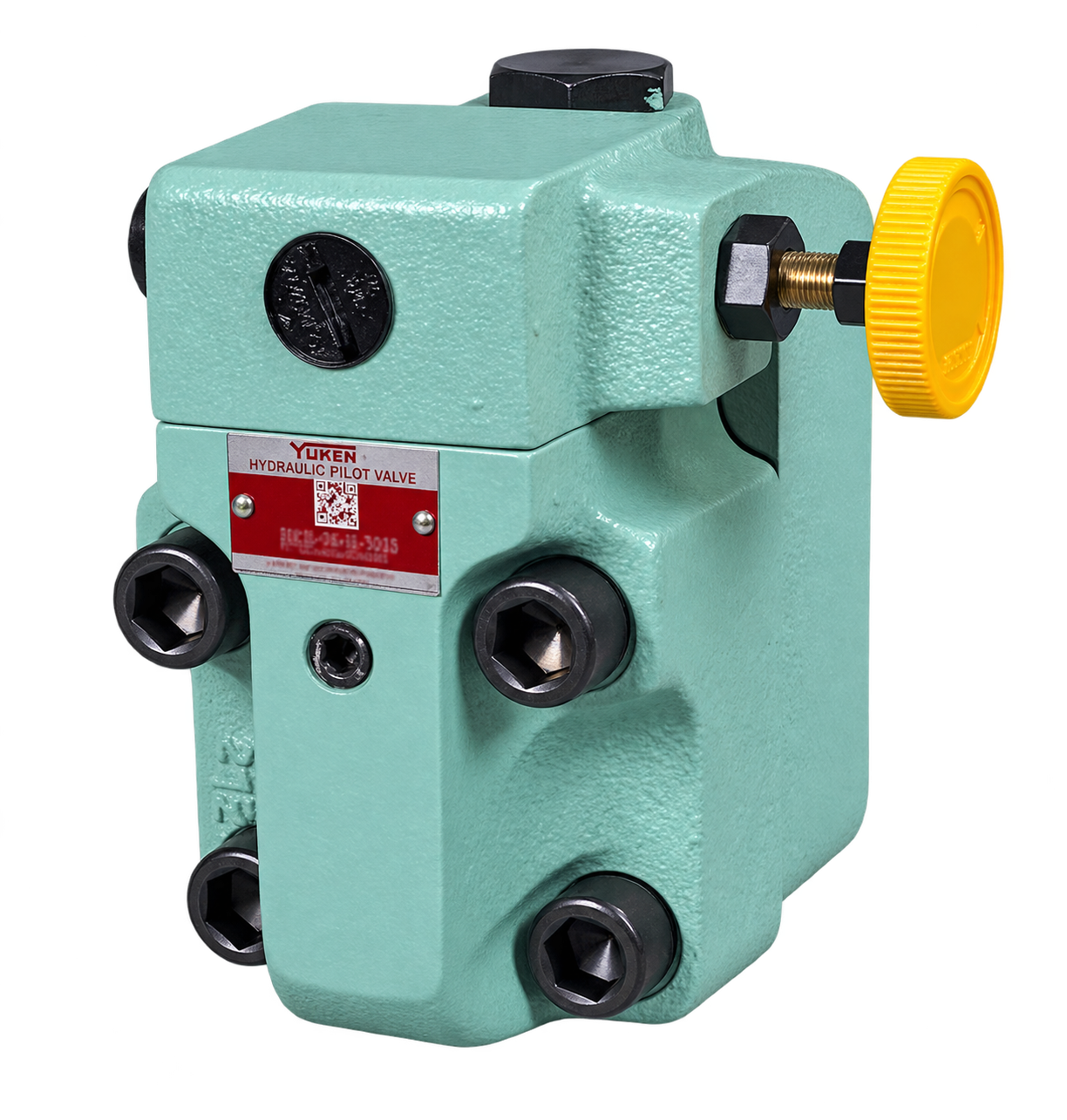
BUCG-06 unloading relief valves allow a pump to run under minimum load in accumulator and two-pressure pump circuits. Selection depends on the required cut-out pressure, operating flow and circuit arrangement.
The range uses size 06 sub-plate mounting. B, C and H identify different cut-out pressure adjustment ranges; the optional V symbol identifies the high venting pressure feature.
Use the catalogue’s cut-in versus cut-out pressure curve when checking the operating cycle. Send the circuit drawing and full valve code with your enquiry so the configuration can be reviewed.
| Parameter | Catalogue value |
|---|---|
| Series and size | BUCG-06 |
| Mounting | Sub-plate mounting |
| Maximum operating pressure | 210 Kgf/cm² |
| Maximum flow | 125 L/min. |
| Valve mass | 12 Kg. |
| Design number / design standard | 30 / 80 |
Confirm the selected pressure range and the circuit’s operating conditions against the manufacturer’s complete catalogue.
| Range symbol | Cut-out pressure adjustment range |
|---|---|
| B | 25~70 Kgf/cm² |
| C | 35~140 Kgf/cm² |
| H | 70~210 Kgf/cm² |
V identifies the optional high venting pressure feature. The manufacturer lists this option for a shorter shift from unloading to onloading. Include the V symbol if it appears on the existing valve.
An F prefix identifies special seals for phosphate ester type fluids. Consult Yuken before ordering this configuration and include the fluid details in your enquiry.
| Item | Catalogue reference |
|---|---|
| Sub-plate | BUCGM-06-2080 |
| Sub-plate thread size | 3/4 BSP.F |
| Sub-plate mass | 4.4 Kg. |
| Mounting bolt kit | BKBUCG-06-20 |
The manufacturer requires a drain connection to the tank, with the pipe end submerged in fluid. In an accumulator circuit, pressure drop between the valve and accumulator must be below 10% of cut-out pressure; drain-port back pressure must be below 2%. Review the full installation instructions and drawings before use.
Selection support
A nameplate photograph and circuit drawing help identify the pressure range, optional features and mounting requirement.
Review model codes, dimensions, installation limits and the cut-in, unloading pressure and pressure-drop curves.
Send your model and circuit details to Shree Hydraulics in Belagavi for product selection and quotation enquiries across India.