
Mounting hardware
Choose the MBK-04 kit from the catalogue's stack-count chart. The kit structure lists M6 and M10 stud bolts and nuts; use the corresponding dimensions and tightening requirements rather than assuming all fasteners are identical.
Yuken stackable hydraulic controls
Compare pressure-reducing, flow-control and pilot operated check modules for 04 Series stacks, with model-specific flow limits.
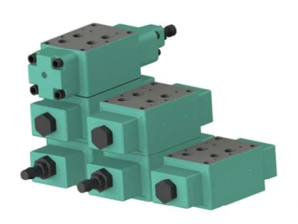
The 04 Series covers modular controls for circuits with flow requirements up to 300 L/min. The catalogue groups reducing valves, throttle and check valves, and pilot operated check valves for use in a stacked arrangement.
Its circuit overview includes a DSHG-04 directional valve. Select the controlled line, pressure range and flow direction before confirming the complete model code, mounting arrangement and bolt kit.
A matching mounting surface alone does not confirm circuit compatibility. Review every valve's function, flow limit and pressure rating as part of the complete stack.
| Detail | 04 Series |
|---|---|
| Valve size | 1/2 |
| Maximum operating pressure | 350 Kgf/cm² for the listed reducing, throttle and check, and pilot operated check models |
| Maximum flow | 300 L/min., subject to the selected model and pressure setting |
| A-range reducing valves | 100 L/min. maximum; check the secondary pressure versus maximum flow curve |
| Mounting bolt kits | MBK-04-01-10 through MBK-04-04-10 |
| Bolt-kit selection chart | One DSHG-04 plus 1 to 4 modular valves, giving 2 to 5 total stacks |
Maximum operating pressure is not the pressure-adjustment range. The reducing-valve flow curves also limit permissible flow at lower secondary pressure settings.
| Function | Model families | Selection detail |
|---|---|---|
| Reducing | MRP-04 / MRA-04 / MRB-04 | P / A / B respectively |
| Throttle and check | MSA-04 / MSB-04 / MSW-04 | A / B / A&B respectively; X for metre-out, Y for metre-in |
| Pilot operated check | MPA-04 / MPB-04 / MPW-04 | A / B / A&B respectively; cracking-pressure codes 2 and 4 |
Select the complete model designation from the catalogue, including the applicable pressure or cracking-pressure code, flow direction, seal option and design number.
| Range code | Adjustment range |
|---|---|
| A | 7 ~ 70 Kgf/cm² |
| B | 15 ~ 70 Kgf/cm² |
| C | 35 ~ 140 Kgf/cm² |
| H | 70 ~ 250 Kgf/cm² |
The catalogue specifies design number 10 and design standard H01 for these valve families. Family names alone are not complete ordering codes.
Choose the MBK-04 kit from the catalogue's stack-count chart. The kit structure lists M6 and M10 stud bolts and nuts; use the corresponding dimensions and tightening requirements rather than assuming all fasteners are identical.
Confirm the DSHG-04 model, controlled lines and the complete hydraulic circuit. X and Y flow-direction options change the throttle and check function; select them from the circuit symbol rather than the product photograph.
Use the catalogue dimensions and circuit symbols to confirm the mounting arrangement and allow space for adjustment and maintenance.
Phosphate ester fluids require the catalogue's special-seal configuration. Consult Yuken before ordering special seals.
Selection support
Share a circuit drawing or clear nameplate photographs so the required functions and configuration can be checked.
Review ratings, circuit symbols, ordering codes, mounting details and dimensions.
Send your valve codes and circuit details to Shree Hydraulics in Belagavi for product selection and quotation enquiries across India.