
N compensator option
N identifies the optional pressure compensator stroke adjustment. The manufacturer lists this option to reduce actuator jumping at start-up. Include it in the model requirement where needed.
Yuken compensated flow controls
Compare pressure- and temperature-compensated flow controls, with or without a reverse-flow check valve. Select the metered flow capacity and pressure rating for your circuit.
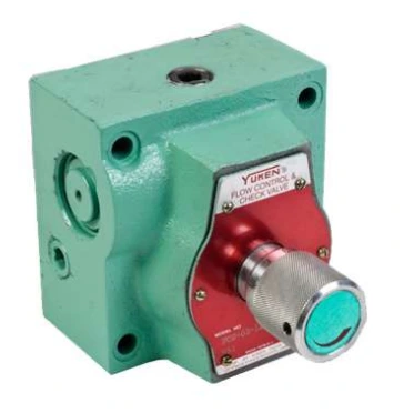
FG and FCG valves compensate for pressure and temperature changes to maintain the selected hydraulic flow within the catalogue operating conditions. Metering flow allows the actuator speed to be controlled.
FG is the flow-control version. FCG adds an integral check valve for controlled flow in one direction and free reverse flow in the other.
Pressure compensation requires a minimum pressure difference between inlet and outlet. The required difference varies with the selected flow, so check the performance curve for the operating point.
| FG / FCG size and capacity code | Maximum metered flow | Minimum metered flow | Maximum operating pressure |
|---|---|---|---|
| 01-1 | 1 L/min. | 0.02 L/min. | 140 Kgf/cm² |
| 01-4 | 4 L/min. | 0.02 L/min.* | 140 Kgf/cm² |
| 01-8 | 8 L/min. | 0.02 L/min.* | 140 Kgf/cm² |
| 02-30 | 30 L/min. | 0.05 L/min. | 210 Kgf/cm² |
| 03-125 | 125 L/min. | 0.2 L/min. | 210 Kgf/cm² |
*For the size 01 capacity codes 4 and 8, the minimum metered flow is 0.04 L/min. at pressures above 70 Kgf/cm². These are metered-flow values; consult the separate reverse free-flow pressure-drop curves for FCG models.
N identifies the optional pressure compensator stroke adjustment. The manufacturer lists this option to reduce actuator jumping at start-up. Include it in the model requirement where needed.
The catalogue includes H01 configurations with a key-operated locking feature. Confirm the complete design number and suffix, since these vary by size and flow capacity.
An F prefix identifies special seals for phosphate ester type fluids. Consult Yuken before ordering special seals and include the hydraulic fluid details with your enquiry.
| Valve size | Sub-plate | Thread size |
|---|---|---|
| 01 | FGM-01X-1080 | 1/4 BSP.F |
| 02 | FGM-02-2080 FGM-02X-2080 FGM-02Y-2080 | 1/4 BSP.F 3/8 BSP.F 1/2 BSP.F |
| 03 | FGM-03-2080 FGM-03X-2080 FGM-03Y-2080 | 3/8 BSP.F 1/2 BSP.F 3/4 BSP.F |
These sub-plates are listed for both FG and FCG. Confirm the mounting dimensions, controlled-flow direction and reverse-flow requirement against the selected model drawing.
Use the catalogue curve to check the available inlet-to-outlet pressure difference at the required flow. Pressure compensation depends on meeting this condition.
For flow adjustments of 2 L/min. or less, the manufacturer specifies a line filter of 10µ or less near the valve inlet. Review the full instructions and the metered-flow-versus-dial-position curve.
The dial adjustment direction differs between size 01 and sizes 02/03. Follow the instructions for the exact model when setting flow.
Selection support
Include the pressure conditions and check-valve requirement so the capacity and configuration can be reviewed together.
Review flow capacities, pressure and viscosity characteristics, dial curves, sub-plates and installation dimensions.
Send your model and circuit details to Shree Hydraulics in Belagavi for product selection and quotation enquiries across India.